NASA Office of Logic
Design
A scientific study of the problems of digital
engineering for space flight systems,
with a view to their practical solution.
SEEQ EEPROM Reliability
Requirements
 Process Technology
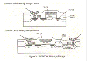
Cross-sections of EEPROM memory storage devices are shown in Figure 1. Programming the logic state of the memory cell is accomplished by charging and discharging a floating gate device (poly 1) via the Fowler-Nordheim tunneling mechanism (a quantum mechanical transmission mechanism of an electron penetrating through the energy bandgap of thin oxide MOS structures). This tunneling occurs through the proprietary oxynitride dielectric beneath the floating gate. The use of oxynitride processing provides fast write/erase times at low internal voltages and the ability for SEEQ to offer high endurance product to our customers. The oxynitride dielectric has low charge trapping and tunnel barrier height characteristics, both of which are superior to the conventional thermal oxide approach.
Memory Cell Design
 The basic SEEQ EEPROM memory cell consists of
a MOS floating gate memory transistor and a select transistor. In 1983 SEEQ
designed the proprietary Q-cell which incorporated a redundancy scheme for the
floating gate device in order to significantly improve device failure rates
under frequent system write conditions. Later, in addition to Q-cell, SEEQ
implemented Q-byte error correction based on a modified Hamming Code. In both
approaches, the memory cell and peripheral logic combine to yield user
transparent memory error detection and correction.
The basic SEEQ EEPROM memory cell consists of
a MOS floating gate memory transistor and a select transistor. In 1983 SEEQ
designed the proprietary Q-cell which incorporated a redundancy scheme for the
floating gate device in order to significantly improve device failure rates
under frequent system write conditions. Later, in addition to Q-cell, SEEQ
implemented Q-byte error correction based on a modified Hamming Code. In both
approaches, the memory cell and peripheral logic combine to yield user
transparent memory error detection and correction.
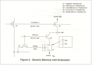
A generic memory cell schematic is shown in Figure2. The logic state of the memory cell is determined by the polarity of the charge stored on the floating gate. A logic "1" corresponds to negative charge and is the result of an ERASE operation. For a logic "0", positive charge is stored on the floating gate following the WRITE operation. The corresponding bias conditions are listed in Table 1. During READ (Sense gate of Q1 at ground - Figure 2) an "erased" cell will be non-conductive, whereas a "written" cell will be conductive. The presence or absence of current at a certain memory location (corresponding to the intersection of a "row" and "a column") is detected by the Sense Amplifier and transmitted to the output buffer as the appropriate logic state.
TABLE 1
|
|
WRITE |
ERASE |
READ |
|
Column Select |
20V |
20V |
5V |
|
Row Select |
20V |
20V |
5V |
|
Sense Line |
0V |
20V |
0V |
|
Bitline |
17V |
0V |
2V |
|
Array VSS |
Floating |
0V |
0V |
|
Floating Gate |
-VP |
+VE |
|
|
VT |
< -5V |
> +2V |
|
Although the internal programming voltage is as high as 20V, only 5V external supply is required, the higher voltages being generated on-chip by charge pumps.
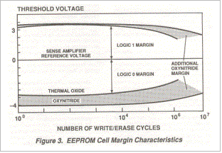 The memory cell thresholds corresponding to
the logic levels "1" and "0" are shown graphically in
Figure 3 as a function of the the number of write/erase cycles. The decrease in
thresholds is significantly reduced by the use of SEEQ's proprietary oxynitride
process - as compared to a standard thermally grown oxide.
The memory cell thresholds corresponding to
the logic levels "1" and "0" are shown graphically in
Figure 3 as a function of the the number of write/erase cycles. The decrease in
thresholds is significantly reduced by the use of SEEQ's proprietary oxynitride
process - as compared to a standard thermally grown oxide.
Through the combined use of the oxynitride process and either Q-cell or the Hamming Code correction techniques, SEEQ is able to offer EEPROMs with typical data retention times greater than 100 years and endurance failure rates less than .01%/1000 cycles.
Reliability Overview
The EEPROM is a nonvolatile memory, hence, it has three operational modes: WRITE/ERASE, READ, and DATA STORAGE. Due to the unique nature of each mode, reliability testing specific to this technology has been developed. The WRITE/ERASE feature is evaluated by extended endurance cycling; the READ mode by standard high temperature dynamic operation; DA TA STORAGE by high temperature bakes. These accelerated stresses are used to determine the device failure rates for each operational mode.
Operating Life Stress
The Operating Life Stress is used to determine the failure rate performance of EEPROM product in the READ mode, FR (READ). Prior to stress, SEEQ programs each device with a checkerboard data pattern. The actual stress is a continuous operating READ mode where the addresses are cycled through all bits in the array. This method conforms to the requirements of MIL-STD-883, Method 1015, Condition D. The stress temperature is either 125 degrees C or 150 degrees C.
For the EEPROM family, the DESC specifications for the Standard Military Drawings (SMD) and JAN level product will also invoke the use of Method 1033 in conjunction with Method 1015. Method 1033 requires an endurance pre-conditioning step, whereby each device is subjected to a number of WRITE/ERASE cycles as prescribed in the individual drawing, prior to the start of the operating READ stress. The operating life test method is an effective means of stressing the peripheral circuitry, as well as the memory cells. This acceleration technique works well for the most common failure mechanisms - defective oxides, metal and polysilicon interconnect failures, and package wire bonds. The operating life failure rate is a good first approximation to that expected in field usage, as the FR (READ) values are greater than FR (ENDURANCE) and FR (RETENTION).
Data Retention
The data retention stress (or unbiased bake) is used to determine the failure rate performance of EEPROM in the unbiased STORAGE or DATA RETENTION mode, FR (RETENTION). Prior to stress, SEEQ programs each device to an erased all logic "1's" pattern, whereby electrons are stored on each floating gate. A stress temperature of 200 to 250 degrees C is used to determine the ability of the memory cell to retain charge over a prolonged length of time. The failure mode is a change in logic state of a memory cell. The failure cause is a defective dielectric, resulting in a loss of charge/electrons from the floating gate. Data retention is considered an operational mode of the product and the data sheet guarantee applies only across the operating temperature range, e.g., for commercial product, the operating range is 0-70 degrees C. The stated storage temperature, usually -65 degrees C to +150 degrees C, in the absolute maximum Stress Ratings section of each data sheet is intended to guarantee that no permanent damage will occur to the package and/or die within a reasonable period of exposure.
Endurance
Write/erase cycling is a stress method used to determine the failure rate performance of EEPROM product in the WRITE mode, FR (WRITE/ERASE). The stress is per- formed at 25 degrees C and utilizes an internal device feature that allows the entire memory to be erased, then written, with one electrical operation, called "block cy- cling." After the device is cycled to the specific limit, data retention bake is performed with the entire memory in the logic "1" erased state (charge on the floating gate) to determine if any dielectric defects were generated that would lead to future data retention failures. An electrical test check is then performed for parametrics, functional, and AC timing. It is important that the post cycle electrical testing is performed to the device specification because there can be failure modes such as access time degradation and peripheral circuit failures not detected by an overly simplistic test. This test method sequence conforms to the requirements of MIL -STD-883, Method 1033. The DESC EEPROM device specifications for Standard Military Drawing (SMD) and JAN level product require a complex matrix of testing where there are groups of devices cycled at each temperature extreme.
The write/erase/bake/test sequence is an effective method of determining the integrity of the tunnel dielectric. Endurance cycling failures are generally caused by dielectric breakdown in the tunnel oxide region. During each write/erase operation, a minuscule amount of charge is trapped in the dielectric through which the programming charge tunnels. The cumulative effect of this charge trapping has strong impact on the effective threshold voltage that the memory cell exhibits after each write/erase cycle. The envelope of the "written" threshold voltage and the "erased" threshold voltage plotted over the number of cycles is referred to as the cell threshold window. Again, referring to Figure 3, the net effect of charge trapping results in an initial widening of the window due to positive charge trapping. Ultimately, negative charge trapping sets the upper limit on endurance when the threshold levels become too close to the sense amp detection level to be useful. The threshold window achieved by using the SEEQ oxynitride process represents an improvement over traditional thermal silicon dioxide of at least a factor of ten. The oxynitride window demonstrates very little closing at 1 million cycles. This performance allows SEED customers the option of specifying an extended endurance limit beyond the standard 10,000 cycle guarantee.
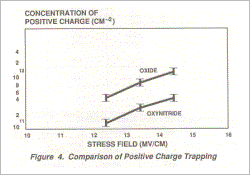
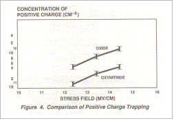 The improved performance of the oxynitride
dielectric is directly related to superior charge trapping characteristics. In
Figure 4, the positive charge trapping characteristics of oxynitride and oxide
dielectrics are compared as a function of field strength. The positive charge
trap density is consistently lower for oxynitride by a factor of four. In
Figure 5 the negative charge trapping characteristics are compared as a
function of total injected charge. The negative charge trapping curves verify
the endurance performance in Figure 3.
The improved performance of the oxynitride
dielectric is directly related to superior charge trapping characteristics. In
Figure 4, the positive charge trapping characteristics of oxynitride and oxide
dielectrics are compared as a function of field strength. The positive charge
trap density is consistently lower for oxynitride by a factor of four. In
Figure 5 the negative charge trapping characteristics are compared as a
function of total injected charge. The negative charge trapping curves verify
the endurance performance in Figure 3.
Techniques to provide high reliability product include the use of redundant tunnel dielectric areas in the memory cell, an oxynitride process in the tunnel dielectric area for high endurance/low failure rate applications, and built-in special test modes for assurance of reliable memory cell operation. The SEEQ Reliability Program has been developed to determine the specific failure rates and failure mechanisms of the EEPROM memories. This data base includes the results from MIL-STD-883/Method 5005 testing, a product monitor sampling plan designed to complement (and supplement) the Military qualification activity, the initial qualification results for new die and packages, and the results of revalidation testing from critical changes to die or packages. The Arrhenius model is used to analyze the data and convert stress conditions to conditions that better represent those found in most operating systems.
|
Home | About | Map
| News&Events | Employment | Contact Us | SEMITEST.DE |
![]()